Fiber products with MPO and MTP connectors – efficiency for dense network environments
Fiber solutions with MPO and MTP connectors offer a high-performance and space-saving option for modern data centers and high-capacity fiber networks. They allow multiple fibers to be combined into a single connector, speeding up installations and improving cabling manageability.
MPO vs. MTP – What’s the difference?
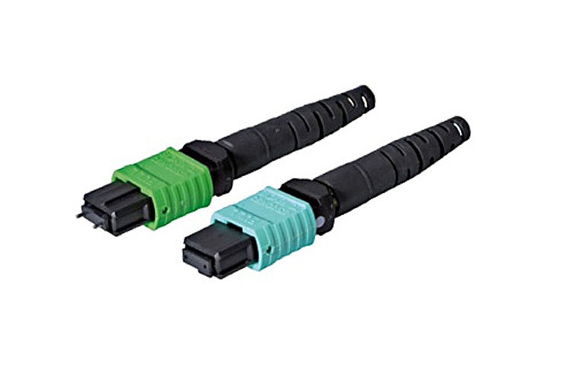
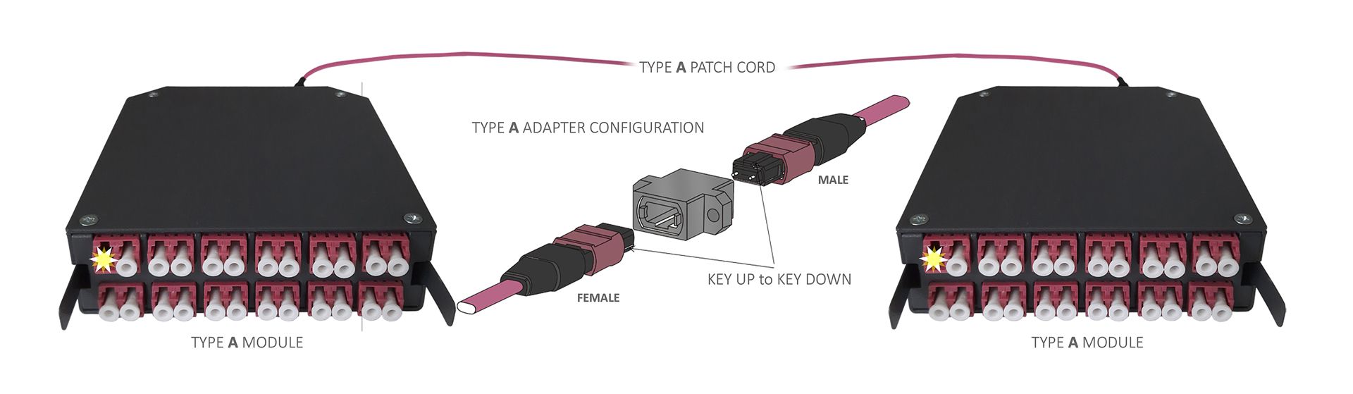
There are two types of MPO/MTP connectors, male and female. The male connector has guide pins and the female connector has holes for them. Male connectors are used, among other things, inside patch panels and for equipment interfaces. The female connector is generally a connector for patch and equipment cables as well as trunk cables.
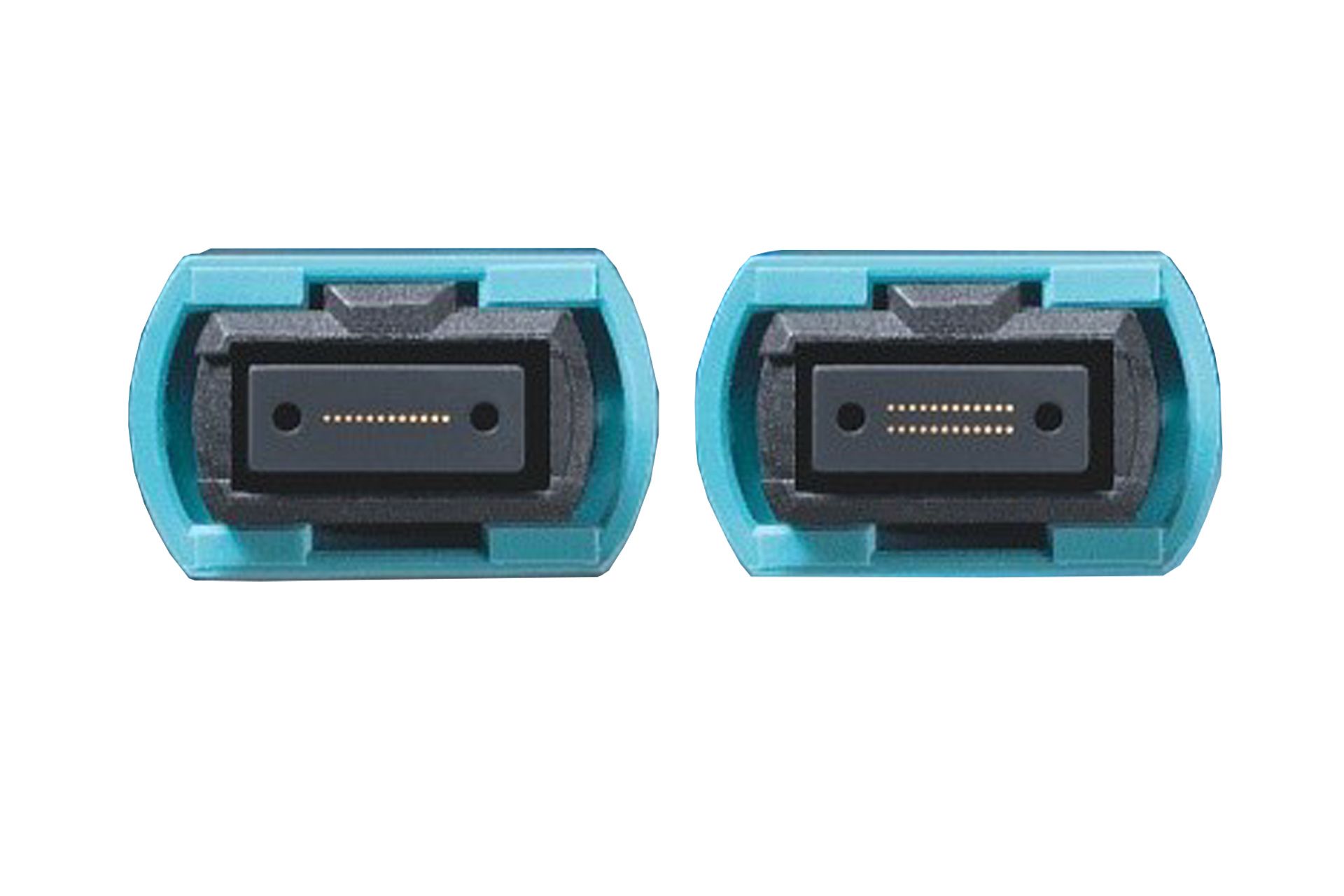
MTP/MPO connectors are available in 8, 12 and 24-fiber versions. The connector size is the same for all fiber counts. The ferrules of the 8- and 12-fiber products both have 12 slots for fibers, of which the middle 4 slots are left unused in the 8-fiber version. This 8-fiber connector is generally only used in multimode products and 40Gb systems.
A 24-fiber ferrule has 12 slots for fibers in two rows.
The 12-fiber connector is currently the most common. The advantages of using a 24-fiber ferrule are the higher connection density, which reduces the number of trunk cables needed by half. The challenges of using a 24-fiber ferrule are the complexity of manufacturing, which increases the price considerably.
Typical insertion losses of MPO/MTP connectors are slightly higher than connectors with normal ceramic ferrules (SC and LC), typically 0.25dB. The return loss is also lower compared to normal ferrules. For this reason, SM MPO/MTP connectors are always APC polished, which results in a typical value of approximately 55dB.
When using these connectors, it is very important to consider polarity right from the design stage. The choice of adapters is also based on polarity. More on polarity below.
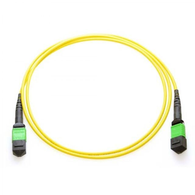
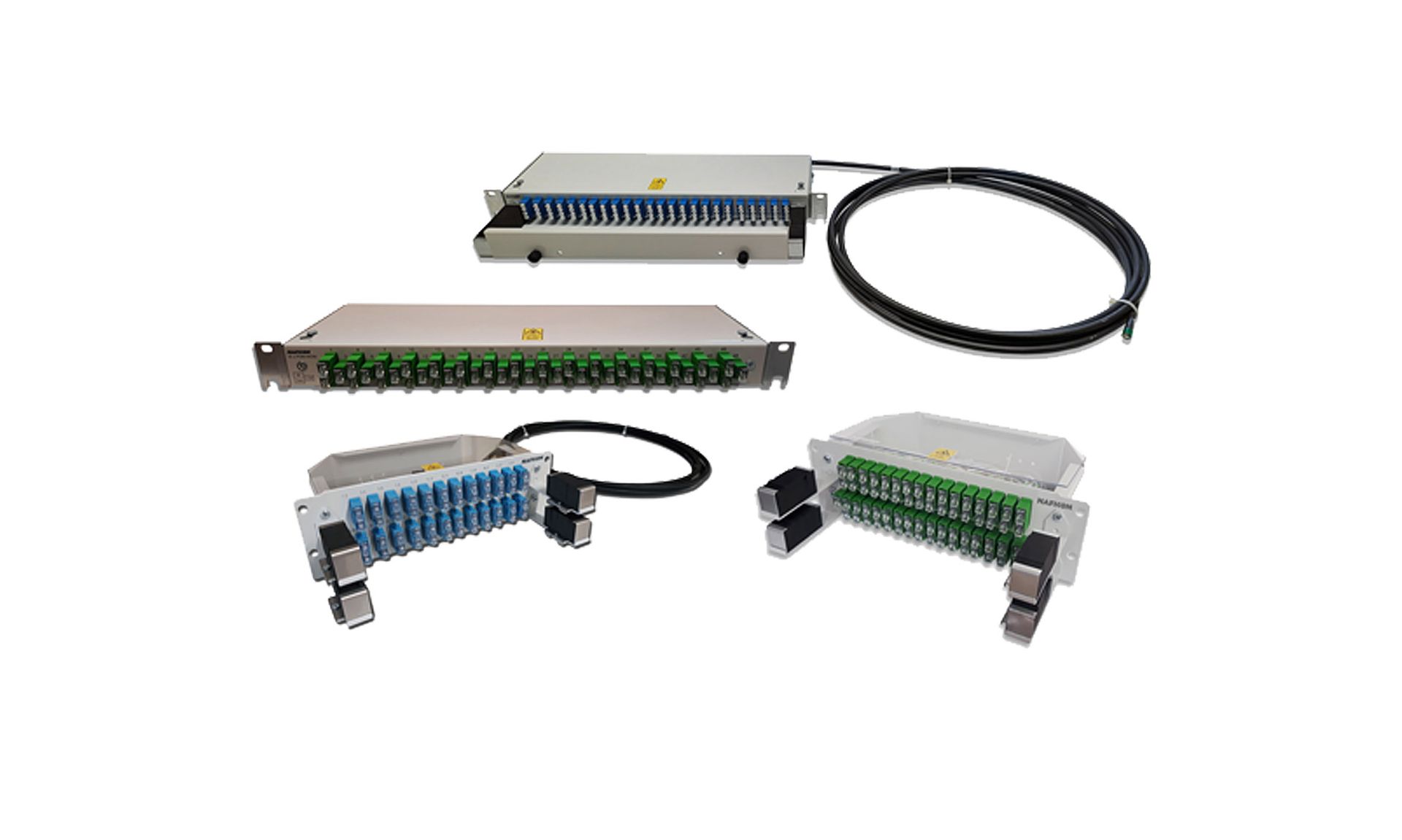
Patch cables
Patch cables are available for all fiber counts, 8-, 12-, and 24-fiber. Both ends can have an MPO/MTP connector, or one end can be equipped with LC or SC connectors. The connectors can be staggered very precisely, so clean installations are easy to make. The length and polarity can be selected as needed, as well as the fiber type (SM, OM3, OM4, and OM5).
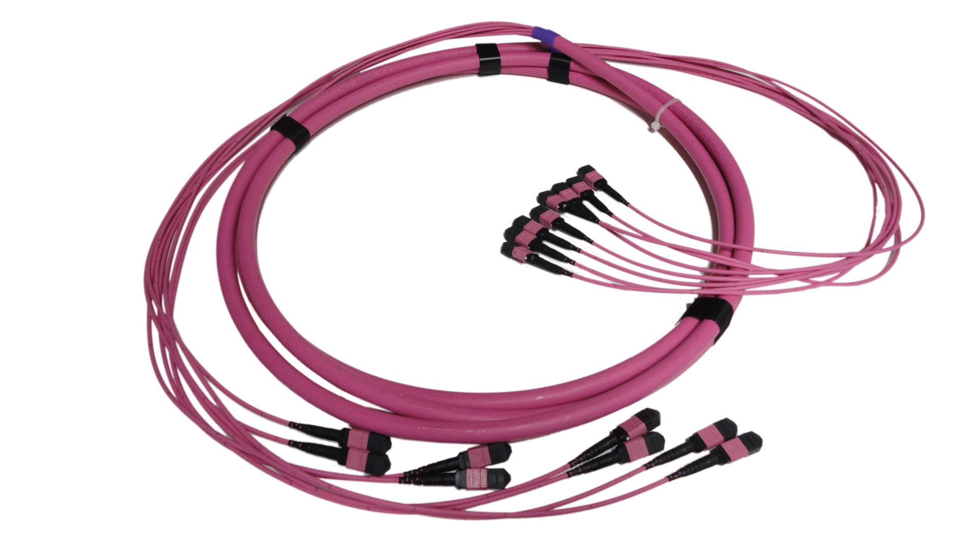
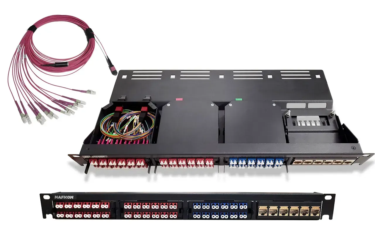
Trunk cables
Trunk cables are available in 12, 24, 48, 72, 96, 144 and 192 fibers. The length of these is freely selectable and the connectors can be on both ends or only on one end.
Polarity
The polarity of MPO and MTP connectors refers to the arrangement of fibers from one end of the connector to the other – the correct polarity ensures that the transmitting fiber (Tx) connects to the receiving fiber (Rx).
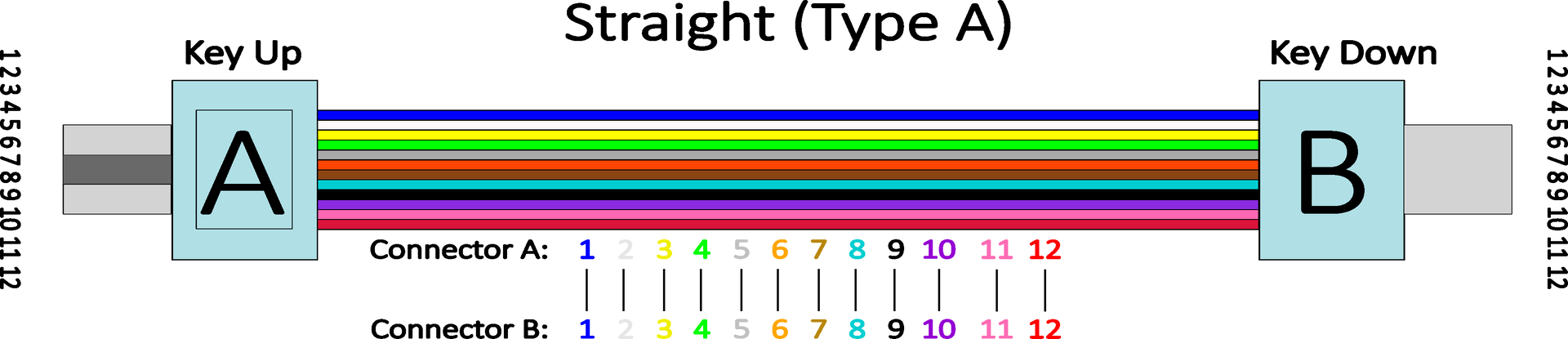
A Type A cable, also known as a straight-through cable, has a key-up connector on one end and a key-down connector on the other end. This means that the fibers maintain the same position on both ends of the cable. The word key refers to the guide notch on the top of the connector that fits into the adapter.
This polarity is common in backbone cables, but requires careful design to ensure the transmitting and receiving ends are connected correctly. If necessary, adapters or reversed connectors can be used to ensure the correct signal direction.
Why Type A?
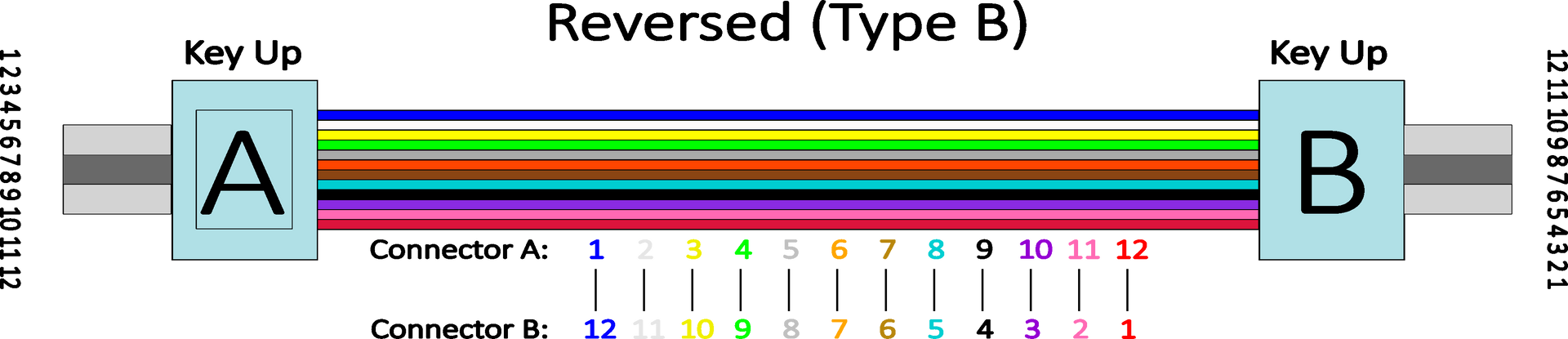
Type B cable, or flipped cable, uses key-up connectors on both ends. This connection method causes the fiber order to be reversed: the fibers switch places at one end of the cable.
This polarity is common, for example, in backbone cabling, where a simple and direct connection is desired without additional adapters, e.g. direct connections from one transmitter/receiver to another. It ensures that the transmit and receive fibers meet correctly when using standardized connection systems. Facilitates rapid deployment and reduces the number of errors.
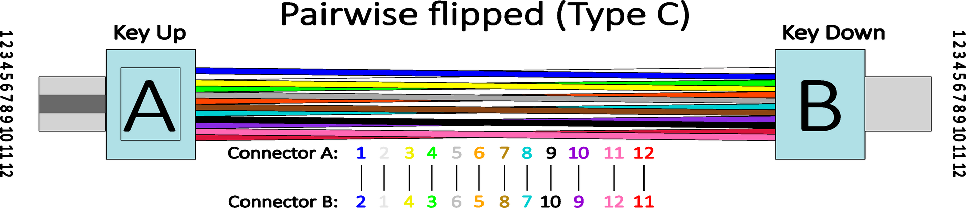
A Type C cable, or twisted pair cable, looks similar to a Type A cable: it has a key-up connector on one end and a key-down connector on the other. However, the fiber arrangement is not straight, and each adjacent fiber pair is twisted at one end of the cable.
Type C cables are specifically used in duplex applications where each fiber pair forms a transmit-receive (Tx–Rx) link. This design allows for direct connection to LC-LC patch cables without additional adapters or manual fiber rotation.