
Product blog
In our product blog you will find articles about Naficon projects, product installations and more generally about trends and changes related to the industry.
Emerging PON technologies
Finland began building optical access networks over 20 years ago using active Ethernet technology. At that time, PON technology was still being shunned in our country, even though it was already widely used worldwide. However, since the 2010s, PON technology has gradually become more common in Finland as its advantages have been realized and the technology itself has developed. Today, PON technology has already established itself as an access network technology and its use is becoming increasingly common and significant. PON technologies are constantly evolving as requirements for speed and energy efficiency increase.
Principles of PON technologies
A PON network is an optical access network in which a fiber connection originating from the telecommunications company's equipment room, i.e. the access node, is divided into several fiber connections using an optical splitter. An optical splitter is a passive component and the PON network also gets its name from this principle of passivity. The abbreviation PON comes from the English term passive optical network, in Finnish passiivinen optikinen verkko. In a passive optical network, there are only passive optical components between the access node and the customer connection. The fiber topology of a passive optical network is point-to-multipoint (P2MP), while the fiber topology of an active Ethernet network is point-to-point (P2P).
The three most important functional parts of a PON network are the central terminal OLT (Optical Line Terminal) located in the telecommunications company's equipment space, i.e. at the access node, the optical network terminal ONU (Optical Network Unit) located at the customer's premises, and a splitter located somewhere in the network between them. The abbreviation ONU is also used alongside the abbreviation ONT (Optical Network Terminal). In practice, ONU and ONT mean the same thing, but in more detail, ONU is a general term for network terminals of one or more users, and ONT is a network terminal of one user.
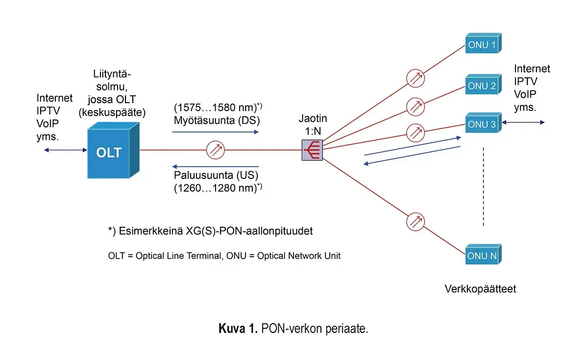
Most PON networks operate with one fiber per connection. The fiber type is the standard single-mode fiber of the telecommunications network (ITU-T G.652.D). The optical fiber originating from the OLT port in the equipment space, or the backbone fiber, is divided into several customer-specific fibers using a passive optical splitter. The splitter's division ratio can be, for example, 1:32, in which case one OLT port in the equipment space and the backbone fiber serve 32 ONU devices. Data communication is possible in one fiber in both directions when different wavelengths are used in different transmission directions. The transmission direction from the central terminal (OLT) to the customer's network terminal (ONU) is called the downstream direction (DS) and the opposite transmission direction is called the upstream direction (US).
Shared capacity and traffic discipline
In the downstream direction, all signals leaving the OLT port pass through the splitter and their power is divided according to the splitter's division ratio into the fibers going to the ONU devices. Each ONU device receives similar signals in the downstream direction. The ONU devices, in turn, identify the signals intended for their own users and forward only these to the user's terminal device or local area network. Addressing and encryption ensure that only the signals belonging to them are forwarded to each user and data security is achieved. In other words, a common transmission capacity is shared in the network and the theoretical maximum speed received by each ONU device depends not only on the speed of the signal leaving the OLT port, but also on the splitter's division ratio. For example, in a 10 Gbit/s PON network, a division ratio of 1:32 results in a theoretical speed of approximately 313 Mbit/s per ONU device.
Traffic, addressing, and encryption required for customer privacy are managed by protocols specific to PON networks. The protocols also allow for prioritization of certain traffic and a certain minimum speed per customer, at least with certain restrictions.
In the reverse direction, a time-sharing based traffic discipline is applied. This means that each ONU can only transmit a signal during the time slot allocated to it. The OLT device controls the network traffic by informing each ONU when it can transmit and what time slot it will be able to use. The OLT device also determines the distance, or more precisely, the signal travel time to each ONU. The travel time must be taken into account when assigning time slots to ONUs. Reverse signals sent by two or more ONUs must not arrive at the splitter at the same time, where they are combined onto the same fiber.
The forward and reverse operations briefly described above are specific to traditional PON networks based on time division multiplexing, or TDM-PON networks. The initial part of the abbreviation TDM stands for time division multiplexing. TDM-PON networks represent the dominant technology of today and the near future, but WDM-PON networks, which are still in the development phase, are already making their appearance.
Most common PON technologies
The history of PON technology goes back over 30 years. The first PON standards were published in the 1990s. However, the development and standardization of modern PON technologies can only be considered to have begun after the turn of the millennium.
The two main organizations involved in PON standardization are the international ITU-T and the US-based IEEE. Table 1 summarizes the most important PON standards published by ITU-T and IEEE and the features they define.
The most common PON technologies used in Finland are GPON and XG/XGS-PON, and it is expected that 50G-PON will become more common in the coming years.
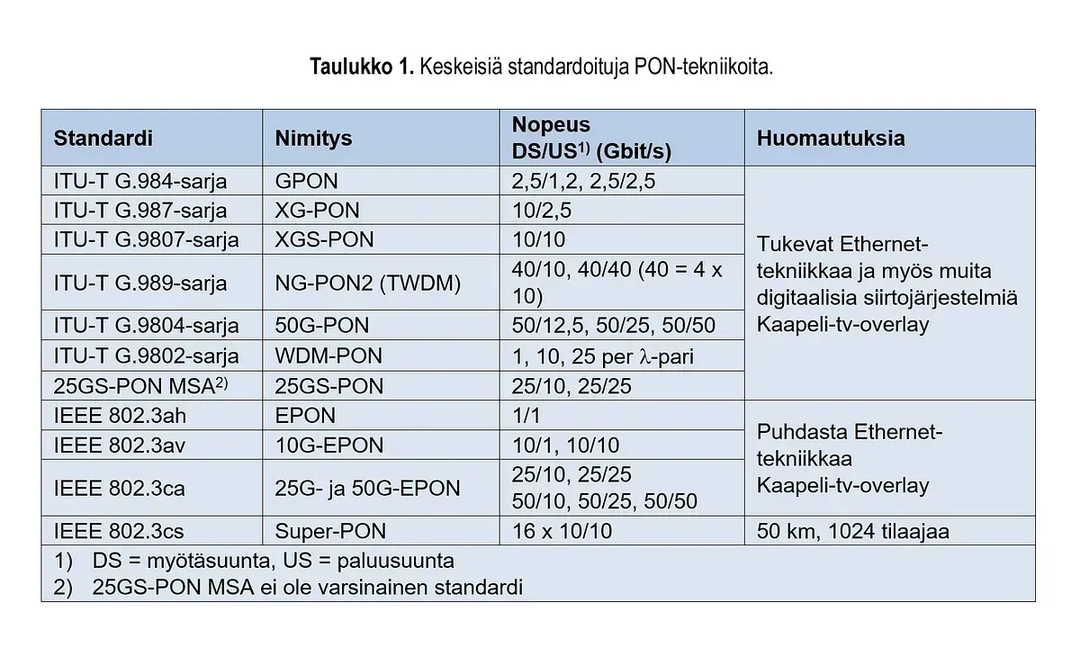
All PON technologies in Table 1 are based on single-fiber connections. Their own wavelengths have been defined for the forward and reverse traffic. The maximum distances between OLT and ONU are 10…40 km depending on the PON technology and the power class of the transmitter used. As a rule, ITU-T PON technologies allow longer distances than IEEE PON technologies. The maximum permitted split ratios also vary by technology and are 32…128, so that ITU-T PON technologies generally have higher maximum split ratio values. The maximum split ratio is naturally also affected by the transmitter power class and the power budget enabled by this, i.e. the maximum permitted attenuation between OLT and ONU. The splitter is a significant attenuation factor, and the higher the split ratio, the higher the splitter’s split attenuation. PON standards define different power classes and corresponding power budgets with minimum and maximum attenuation. The maximum attenuation varies between 20…35 dB depending on the PON technology and transmitter class.
In GPON, XG and XGS-PON technology, it is also possible to use a bidirectional optical amplifier in the backbone fiber, which can increase the maximum distance to 60 km. In this case, it is still a PON network, although the principle of passivity disappears with the optical amplifier.
Figure 1 and Table 2 show the physical layer characteristics of XG-PON and XGS-PON networks.
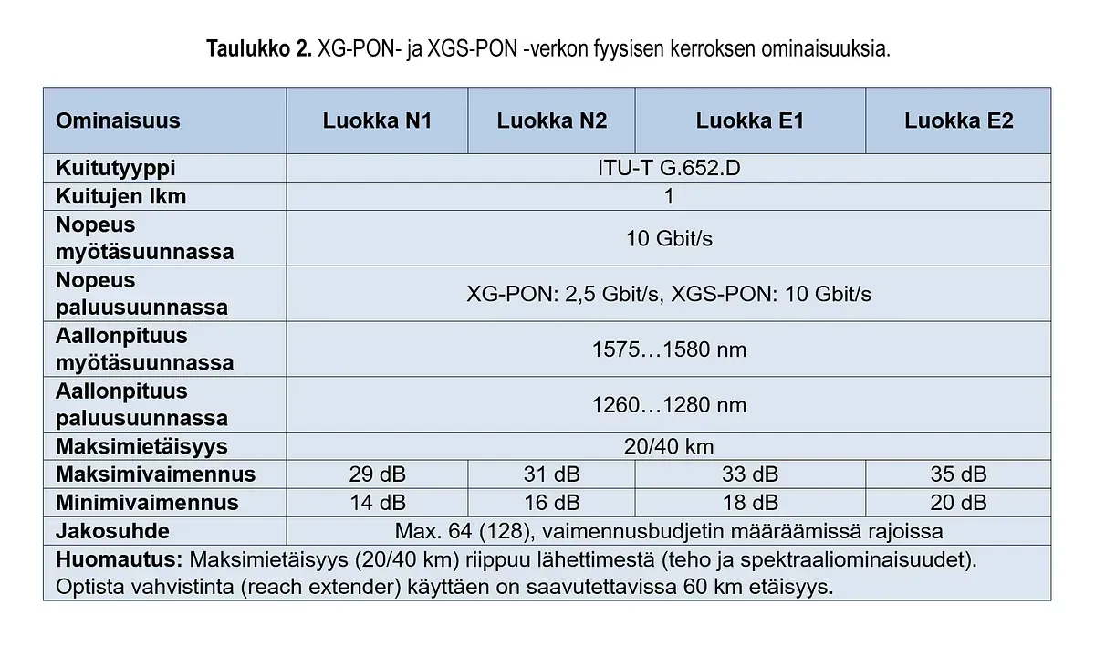
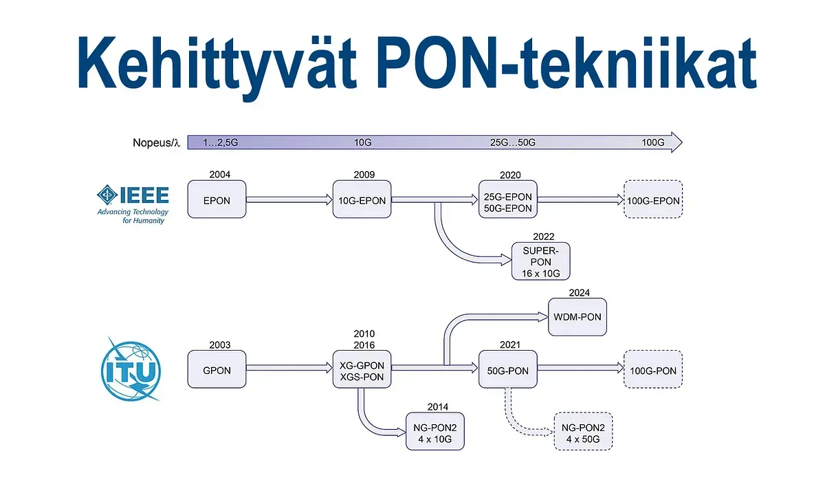
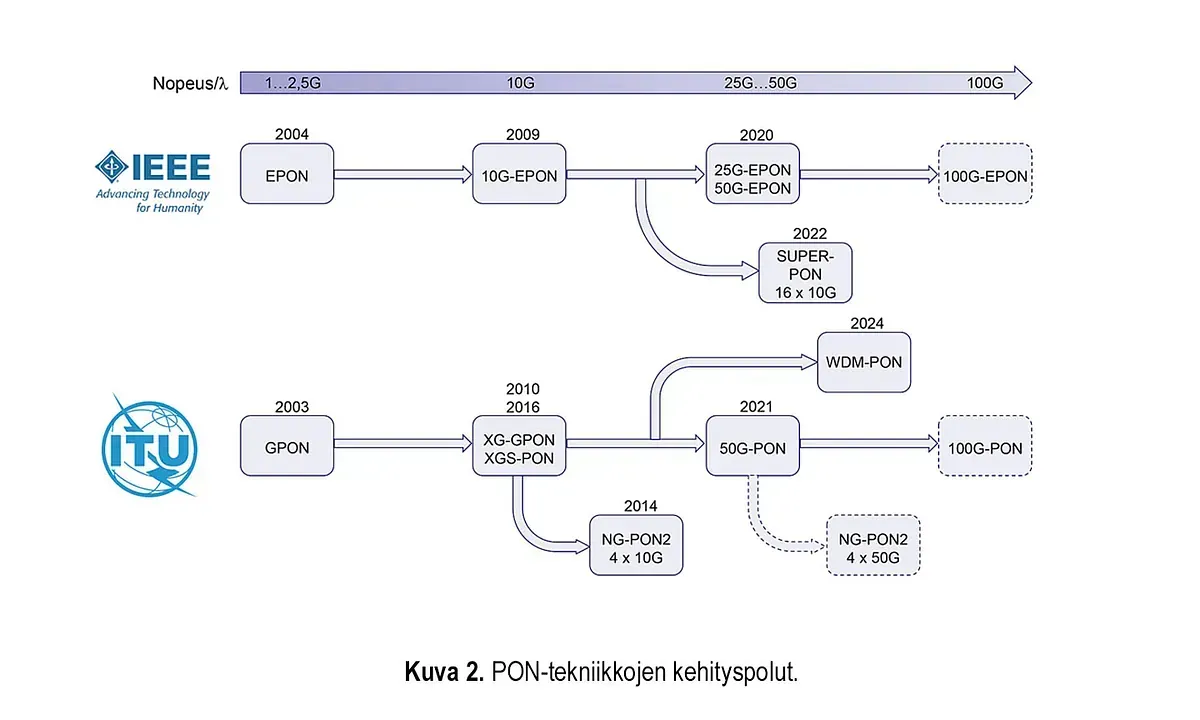
Figure 2 shows the development paths of PON technologies in this millennium. The speed per wavelength has already increased to 50 Gbit/s. The speeds are still increasing and the next one is 100G-PON, for which pilots are already underway. WDM-PON technology is also gradually becoming marketable and the first standards are already ready. An intermediate stage in the development from TDM-PON and pure WDM-PON is TWDM-PON, which combines traditional TDM-PON and WDM technology. NG-PON2 represents such a PON technology. Both TDM and WDM technology are also applied in the so-called Super-PON. In the following, we will take a closer look at the aforementioned PON technologies, which achieve transmission speeds of over 10 Gbit/s.
50G-PON
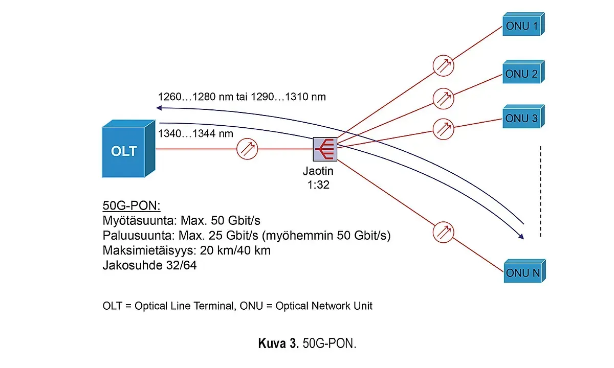
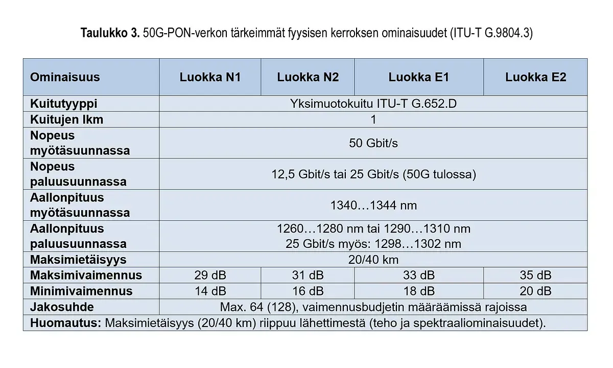
50G-PON is the next natural evolution after XGS-PON. The 50G-PON network technology standardized by ITU-T is defined in the ITU-T G.9804 specification series. Its main physical layer characteristics are shown in Figure 3 and Table 3.
The IEEE, which sets Ethernet standards, has also published a 50G-PON standard. This standard is IEEE 802.3ca. There are technical differences between the ITU-T and IEEE 50G-PON networks. The most significant differences are as follows:
- The ITU-T 50G-PON network has reverse speeds of 12.5 Gbit/s and 25 Gbit/s, and in the future also 50 Gbit/s. The IEEE 50G-EPON network has reverse speeds of 10 Gbit/s, 25 Gbit/s and 50 Gbit/s. The IEEE network also has a 25 Gbit/s option in the forward direction.
- In the ITU-T 50G-PON network, the speed of 50Gbit/s is implemented using the principle of a single wavelength. In the IEEE 50G-EPON network, the speed of 50 Gbit/s is implemented as the sum of two 25 Gbit/s speeds, which means that two wavelengths are needed to create a speed of 50 Gbit/s.
Both the ITU-T 50G-PON network and the IEEE 25G/50G-EPON network have different options for reverse speeds, allowing for simultaneous GPON or XG(S)-PON on the same network.
TWDM-PON
The evolution from pure TDM-PON technology to pure WDM-PON technology does not occur without intermediate stages. The intermediate form is PON technology, which combines features of both technologies. Figure 4 shows a TWDM-PON network, which consists of four TDM-PON networks “stacked” with WDM technology. Each TDM-PON uses its own wavelengths. TWDM-PON is therefore a combination of WDM and TDM-PON technologies.
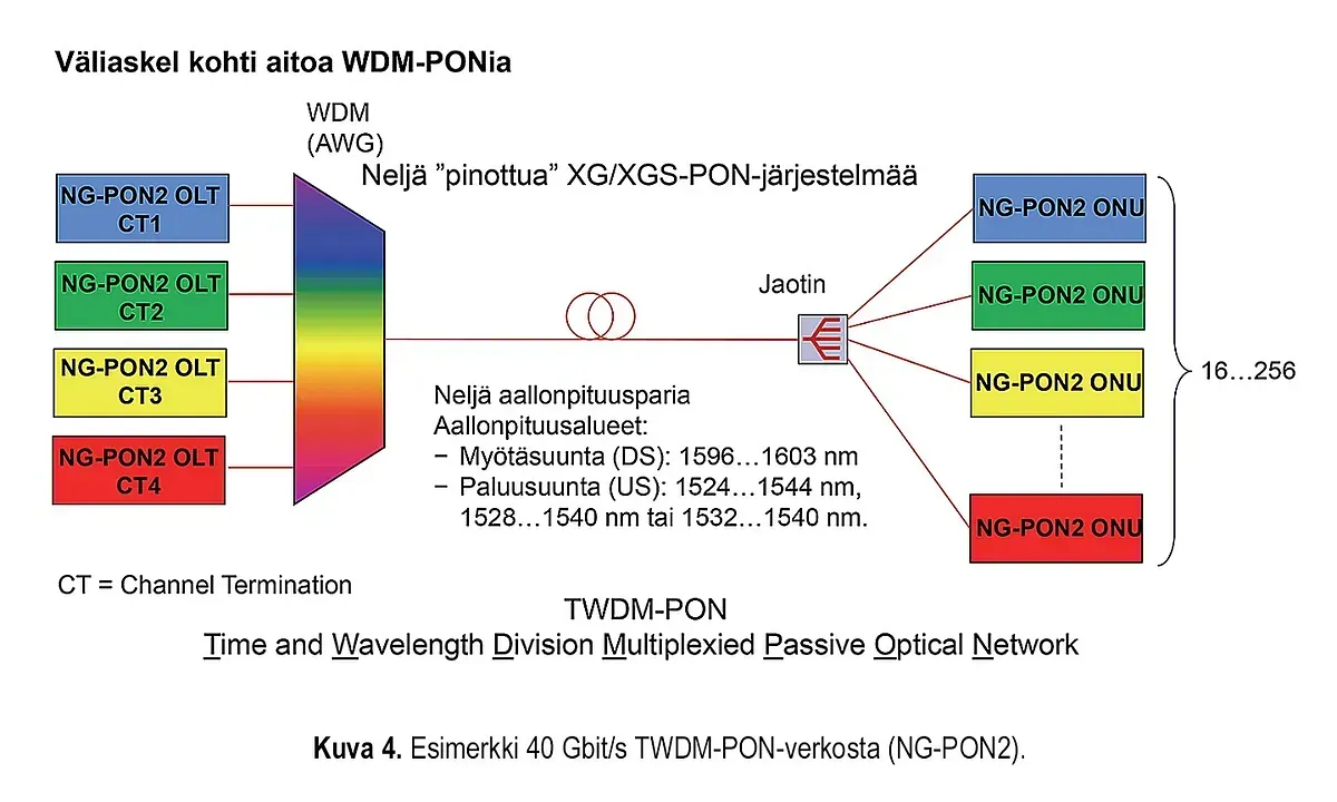
ITU-T has published TWDM-PON specifications in the G.989 series. In these specifications, the technology in question is referred to as NG-PON2. The name of the ITU-T G.989 specification series is: 40-Gigabit-capable passive optical networks (NG-PON2). The specifications (recommendations) define, among other things, general requirements and physical layer characteristics for TWDM-PON technology, which supports speeds of 40 Gbit/s in the forward direction (DS) and 10 Gbit/s in the reverse direction (US).
Physical layer features of ITU-T NG-PON2 network:
- Speeds/CT: 10G/10G, 10G/2.5G, or 2.5G/2.5G (XG-PON or XGS-PON)
- Four attenuation classes: N1: 29 dB, N2: 31 dB, E1: 33 dB and E2: 35 dB
- Maximum distance: 20 km and 40 km
- Number of shares: 16…32…64…128…256
- Wavelengths DS/US: 1596…1603 nm / 1524…1544 nm
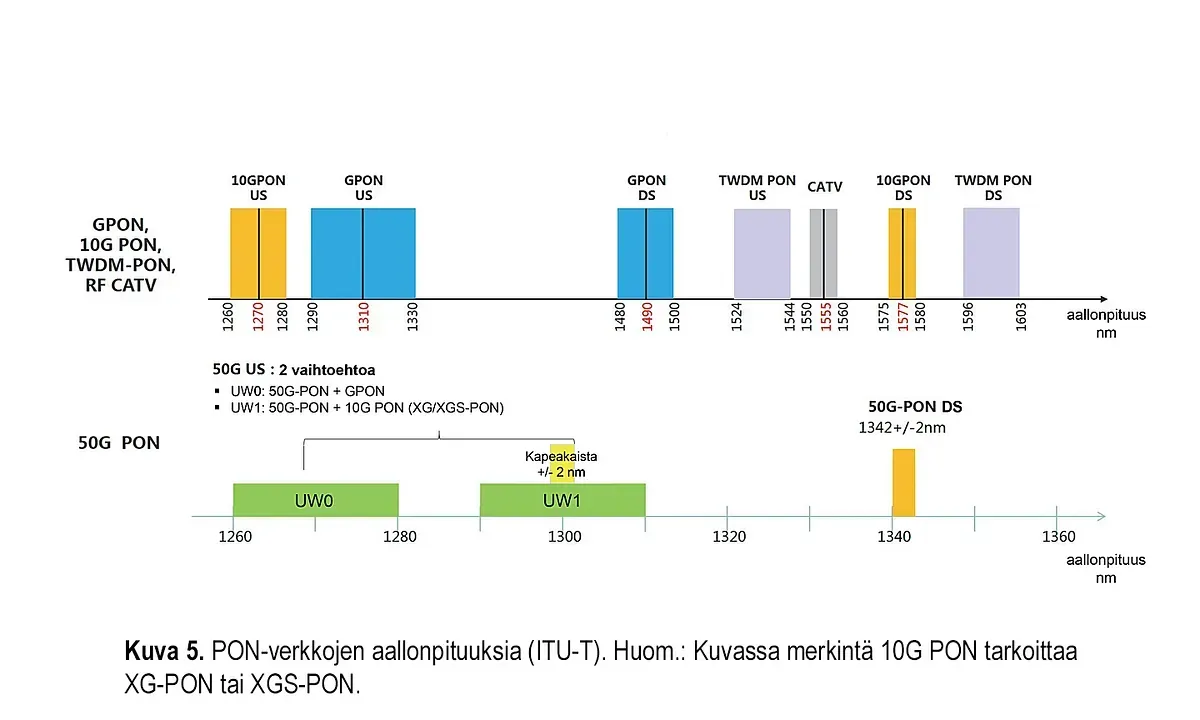
PON wavelengths
The wavelengths used in PON networks have been standardized in a coordinated manner so that EPON and GPON use the same wavelengths, and 10G-EPON and XG/XGS-PON use the same wavelengths, but different wavelengths compared to the first mentioned (EPON and GPON). In addition, 25G and 50G-PON and NG-PON2 use different wavelengths compared to all of the above. This makes it possible for the same physical optical access network and even its same fibers to have, for example, GPON and XG(S)-PON, GPON and 50G PON or XG(S)-PON and 50G PON simultaneously without any interference from each other. This means that the network can be easily upgraded to higher speeds using the same fibers, taking into account the attenuation budget. In addition, cable TV (DVD-C/C2) has its own wavelength range (1550 …1560 nm).
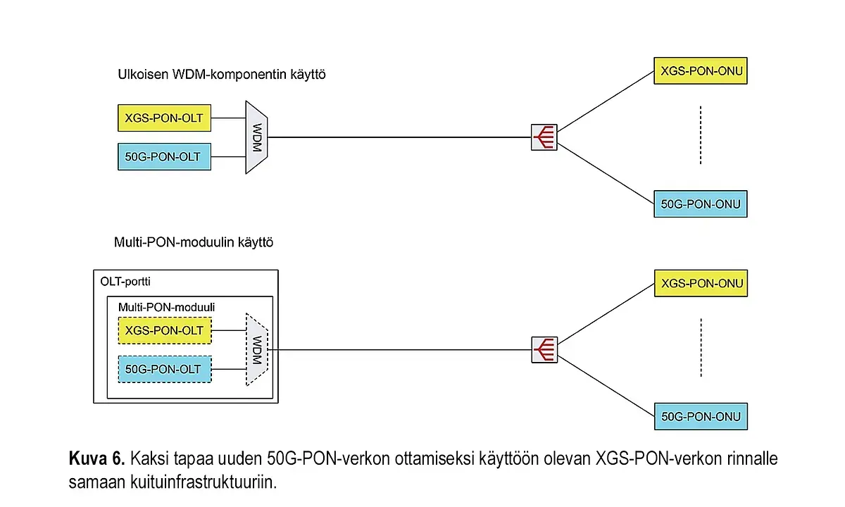
There are two ways to connect two PON systems to the same fiber infrastructure. In the traditional way, the OLTs of the networks are connected to the same fiber using a WDM component. This requires an additional component external to the OLT devices, which requires a certain amount of space and also causes approx. 1 dB of attenuation. The second way is to use OLT optics, in which the OLT functions of the networks to be connected and the WDM connecting them are integrated into the same module, called a multi-PON module. In this case, no external connecting component is required, but only the installation of the multi-PON module in the existing frame. Figure 6 shows these methods in the case where a new 50G-PON is deployed alongside the existing XGS-PON in the same physical fiber infrastructure.
Super-PON
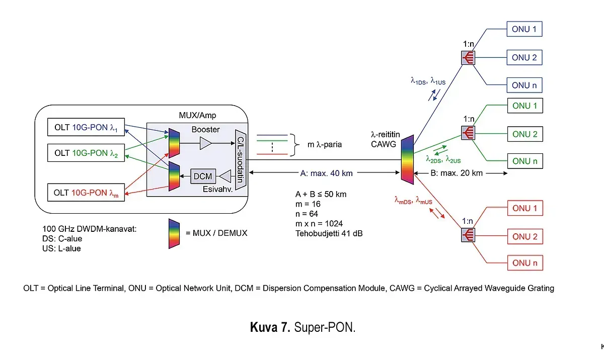
At the end of 2022, IEEE published the IEEE 802.3cs standard, which defines a PON network called Super-PON. Super-PON is based on both TDM and WDM technology. It can achieve a distance of 50 km and the number of ONUs can be up to 1024. The speed is 10 Gbit/s in both directions. The principle of Super-PON is shown in Figure 7. The key elements and their functions are as follows:
- The center houses a MUX/Amp equipment to which 16 OLT modules can be connected. Each OLT module transmits and receives at a speed of 10 Gbit/s on its own wavelength pair (λmDS and λmUS, m = 1…16).
- The outgoing wavelengths are multiplexed and amplified, and then fed through a filter into a single backbone fiber. The filter separates the C- and L-band wavelengths. The forward direction (DS) uses C-band wavelengths and the reverse direction (US) uses L-band wavelengths.
- A λ router is located at a maximum distance of 40 km from the center, which divides the wavelengths into 16 fibers: one wavelength per fiber.
- At a distance of up to 20 km from the λ router, there is a splitter with a splitting ratio of up to 64.
- The structure of the ONUs is simpler than in the NG-PON2 network (Figure 4), because each ONU receives only one wavelength. Thus, there is no filter in the ONUs.
- In the return direction, the wavelengths (16 wavelengths) coming from the ONUs through the splitters are combined into the backbone fiber in the λ router.
- The wavelengths returning from the trunk fiber to the exchange are passed through a C/L filter to a preamplifier, a dispersion compensation module and further to a demultiplexer, which divides the wavelengths into separate ones. These 16 wavelengths are each received in its own OLT module.
The Super-PON network therefore has 16 TDM-PON networks, each operating on its own wavelength pairs and at a speed of 10 Gbit/s. The total number of ONUs is 16 x 64 = 1024.
The maximum distance between OLT and λ router is 40 km and the maximum distance between λ router and ONU is 20 km. Note that the maximum distance between OLT and ONU is 50 km (not 60 km). The maximum attenuation between OLT and ONU is 41 dB.
WDM-PON
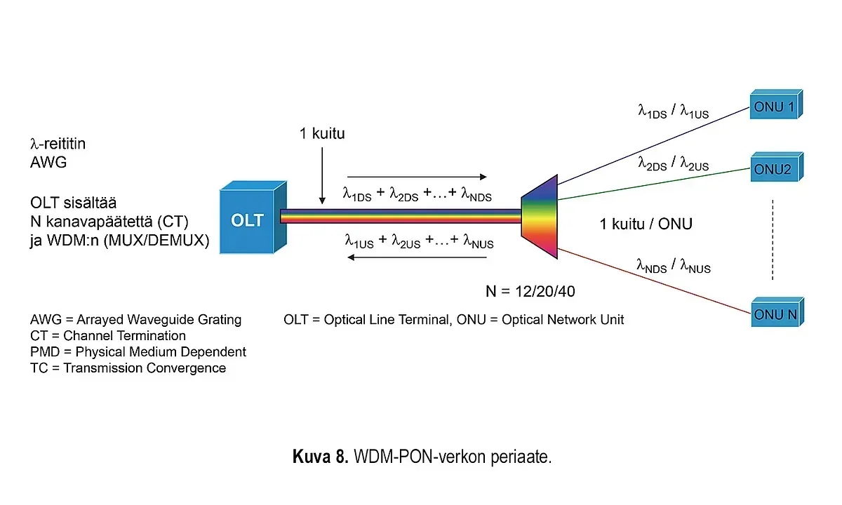
Traditional PON networks, such as G-PON, XG(X)-PON and also the newer 50G-PON, are TDM-PON networks, because in them the return traffic is managed and channelized using time division multiplexing (TDM). Another way to divide the capacity of the same fiber is wavelength division multiplexing (WDM). PON networks that utilize this technology are WDM-PON networks. The principle of a WDM-PON network is shown in the form of an example in Figure 8.
WDM-PON networks are still in the development stage, but the first standards are already ready. These networks are very promising and have undeniable strengths and advantages. The main advantages are as follows:
- Transparent end-to-end connections from OLT to ONU and from ONU to OLT.
- Point-to-point wavelengths ensure sufficient capacity and data security
- It is easy for users to implement different transmission speeds and services independently of others, and changes or updates to them can be made without disturbing other users.
The example in Figure 8 represents a WDM-PON network according to the ITU-T G.9802 standard series. The mentioned standard defines, among other things, the following features:
- 12/20/40 point-to-point wavelength pairs
- DS: 1529,553-1544,526 nm; US: 1550,116-1565,496 nm
- Channel spacing 100 GHz (~ 0.8 nm)
- AWG splits/combines wavelengths in both directions
- Colorless (tunable) lasers
- 1/10/25 Gbit/s for each ONU
- 10km/20km
More detailed physical layer characteristics and requirements, as well as requirements for upper layers, are defined in ITU-T G.9802.2 and other parts of the standards suite.
Achieving cost-effective and reliable WDM-PON technology still requires development and standardization. However, in a few years, WDM-PON will become a marketable and viable access network technology. Key components and related issues in WDM-PON technology include transmitter lasers and WDM splitters.
The many different wavelengths required in WDM technology can be achieved using various alternative technologies. At present, tunable lasers, whose wavelength can be tuned to the desired wavelength using electric current or temperature, seem to be the most promising. There are also other technologies. These include injection-locked lasers, reflective lasers, and broadband light sources whose spectrum is sliced.
Separate fixed wavelength lasers, or so-called color lasers, are hardly an option because they are neither logistically nor economically advantageous.
In a WDM-PON network, the splitter is a WDM splitter, which in the forward direction filters only one wavelength from the set of wavelengths propagating in the trunk fiber to each ONU fiber and in the reverse direction combines the different ONU wavelengths into the trunk fiber. There are alternative technologies to implement this, the most promising and common of which is the arrayed waveguide grating (AWG). This technology also enables bidirectional operation so that ONU-specific wavelength pairs (forward direction/return direction) can be used.
The advantages of a PON network are both technical and economic.
The main advantages of a PON network are related to passive distribution. Since the splitter is a passive component, it practically does not require any maintenance. Therefore, maintenance in a PON network is easy and maintenance costs are low. Active devices are only present in the access node and at the customer. In an active Ethernet network, on the other hand, active devices (Ethernet switches) are often also present inside the network “in the field”. The splitter can also be easily placed in an outdoor cabinet and does not require a power supply. PON technology can also be used efficiently to utilize fiber capacity. Especially in networks with few fibers, PON is often a clear alternative to a pure star-like active Ethernet network. In the access node, PON network devices also take up significantly less space than Ethernet switches. In a PON network, one port can serve up to 64 customers, while in a full star-like active Ethernet this requires 64 ports.
The applications and services of a PON network are mainly digital and especially IP/Ethernet applications. However, the PON standards also reserve the wavelength range 1550…1560 nm for other services. A typical such service is optical cable TV transmission (in the downstream direction). WWDM technology is used to combine data and cable TV signals on the same fiber and separate them from the same fiber. The PON network therefore also supports cable TV transmission on the same fibers as Ethernet data.
Shared capacity has often been considered the biggest shortcoming of PON networks. However, capacity adequacy can be taken into account by sizing the number of ONUs and providing a sufficiently large total capacity. As technologies have developed, the PON capacity of a single OLT port in the downstream direction, for example, has increased from the 1 Gbit/s speed of the EPON network in 2004 to up to 50 times, and the development continues.
What about internal networks?
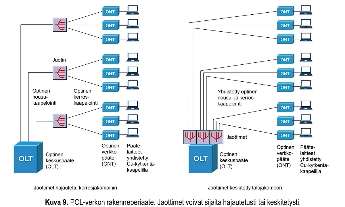
PON technology can also be applied in smaller networks, such as local area networks in buildings. The concept of Passive Optical LAN, or POL or POLAN for short, has appeared increasingly in international press and web articles and presentations in the field.
Passive Optical LAN (POLAN) is based on the same technologies used in optical access networks, which are described earlier in this article. The three main network components characteristic of a POL network are therefore an optical central terminal typically located in a building distribution center, an ONT located on the user's premises near the user's terminal, and a splitter located somewhere in the network between these.
The POL network is completely optical between OLT-ONT and there is no electronics on this part of the network. The user or other network terminal is connected to the ONT device, for example, with a category 6A patch cable. The number of RJ45 ports on the ONT device is typically 1...4, but can also be, for example, 8, 12 or even 24. A WLAN access point can also be connected or integrated into the ONT device.
Splitters can be placed, for example, in floor distribution boxes, but other placement options are also available. The split ratio can be, for example, 1:32, in which case one OLT port and trunk fiber serve 32 ONT devices. The location of the splitter in the POL network should always be chosen according to what is most appropriate. The selected option affects, among other things, the number of fibers required in the riser cables, the space utilization of the distribution boxes, and the connections in the distribution boxes.
The POL network requires both optical riser and layer cabling. The fiber type is OS2 and the connector type is primarily LC connector. The connectors in the cabling must be APC ground. The same applies to the connectors in the distribution panels.
Optical layer cabling is terminated in a telecommunications box equipped with APC-polished LC connectors or, for example, at a centralization point installed at the top of a cable tray. From the centralization point, cabling can be continued using a socket pole, just like in paired cabling. In this case, the optical telecommunications box is at the bottom of the pole. The ONT device is placed near the user and connected to the telecommunications box with an optical patch cable and to the user or other terminal device with a category 6A patch cable.
The ONT can also be placed up close to the optical hub. The hub requires a housing with both fiber and copper terminations to terminate both cable types and make the connections. This effectively creates a small distribution box, which can be called a zone distribution box. It can serve multiple users depending on the number of Ethernet ports (RJ45) on the ONT. The copper cabling at the end can also be replaced with WLAN technology if a WLAN access point is connected or integrated into the ONT.